Cold supply can be carried out both from the refrigeration station and the refrigeration plants. The refrigeration scheme is a circuit of interaction of cooling stations or plants with users of refrigeration. When developing refrigeration schemes, the design engineers seek to create optimal conditions of the system operation. Thus, this is, first of all, the approximation of a cold to its users of refrigeration, which substantially compensates and reduces the loss of cooling and additional energy consumption associated with the hydraulic losses.
 According to the heat-rejection method, there are two main schemes of cooling supply:
- A cooling system with the direct expansion of refrigerant in the processing units;
- A cooling system with the intermediate coolant (‘brine’ cooling).
A mixed scheme is also used, in which part of the process is cooled directly by the evaporating refrigerant agent, and partly − by the intermediate refrigerant. A system of refrigeration with the direct evaporation can be either with the pump supply of refrigerant or without it. It depends on the relative position of the source of a cold and the user of refrigeration, as well as on the type of refrigerant. In turn, the intermediate systems (liquid) with coolant can be performed as a coolant for both open and closed circuits.
Classification of refrigeration systems
In food industry the cooling systems are used a large variety of schemes of supplying refrigerant. These are straight-flow coolant devices with:
- parallel and consecutive bottom- and top-feed;
- liquid separators and supporters;
- steam driers and superheaters, etc.
In the chemical and petrochemical industry the schemes are not so different, but they differ in the extent of cooling capacity, a variety of refrigerants and temperatures used a cold.

Scheme with Direct Expansion in Technological Devices (Direct Cooling)
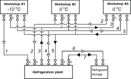
Principle diagram of the relationship of the cooling station with the process areas, using two parameters of a cold, is shown in the lower Figure.
 Scheme of pipeline links of the cooling station with the process areas when the wares are cooled down by the direct expansion inside the technological devices:
- Plant floor №1 consumes chill -12 °C, plant floor №2 and plant floor №3 consume chill 0 °C. In such scheme of a cold supply the cooling condensing units are located on the cooling station. The technological apparatus are used directly as evaporators in the shops.
- Refrigerant vapor with a temperature of -12 ° C is sucked off by the compressors or absorbers of the refrigeration station via Pipe-line 1.
- Pipe-line 2 is just the same operation, but the vapor − with a temperature of 0 °C.
- Pipe-line 3 serves to supply liquid refrigerant to the shops. The diameters of these pipe-lines are determined from the thermal and hydraulic calculations.
- Pipe-line 4 is intended for conducting the auxiliary operations in the apparatuses of technological workshops (suction of vapors, transfer of liquid refrigerant by high pressure pairs). The diameter is 50-100 mm.
- Pipe-line 5 serves to free the technological equipment from the liquid refrigerant or reflux. The diameter is found from the calculation of the rapid release of the system from the liquid (for example, for 1 hour, if the time is not specified by the technical conditions).
- Pipe-line 6 is laid in the event that there is no compressor in the refrigerant warehouse. It is fed with vapor under the pressure to retransfer the liquid refrigerant from the warehouse to the refrigeration system.
- Pipe-line 7 serves for supplying the liquid refrigerant from the warehouse to the station and back.
As a rule, a single block of capacitors is installed to condense the refrigerant, which is equipped with a single water supply system and a condensate collection system. This allows the liquid refrigerant to be supplied to all plant floors through a common pipe-line and with parameters that are independent of the temperature of the chill.
Cooling with intermediate refrigerants
In this scheme, as a rule, the completely assembled refrigerating machines are installed at the station. A refrigerant does not extend beyond the station, which increases the reliability and safety of the system. Chill is transported to the user of refrigeration by an intermediate coolant. A communication between the refrigeration station and the plant shops is carried out, depending on the number of chill parameters, with the help of 2-3 pipe-lines.
 Scheme of pipe-line communication between the plant shops and the cooling station in refrigeration, using the intermediate refrigerants
This cooling system shows both users of cold and a refrigeration station. In accordance with the scheme:
- Through the pipelines 1 and 3 a refrigerant with the temperatures of -12 to 0 °C enters the plant shops and supplied to the users of refrigeration;
- Through pipelines 2 and 4, the same refrigerant, but heated up to 3-5 °C, returns to the station into the evaporators of refrigeration units;
- Through the pipeline 5 the coolant is draining (natural flow) when the system has become empty or overflowed;
- Through the pipeline 6 XH the refrigerant is pumped from the warehouse to the station and vice versa.
If a refrigerant is the water, the pipeline 5 is not laid. The water is simply pouring out into a sewer. Feed of coolant can be performed as on the closed circuit, and on the open one – with a jet break.
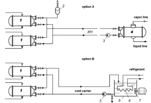
Circuit cooling systems with intermediate refrigerants
 Option A – closed-circuit;
Option B – open loop (with a breakdown of the jet).
1 − technological devices (consumers cold); 2 − expansion tank; 3 − circulation pumps coolant (HN); 4 − chiller tube bundle; 5 − tank panel evaporator; 6 − panel evaporator; 7 − stirrer.
The open cooling system is more convenient for using than the closed type, especially if the water is used as a coolant. Use of water as coolant in open schemes has several advantages. In winter the river water with a temperature of 4-6 °C can be fed into technological devices and sent, already heated, to the in-plant recirculation system. In such system it is advisable to use the river water for cooling the compressors and the refrigerating machine apparatuses, because it is at 5-10 °C lower than the back. This contributes to significant energy savings. When transporting chill with negative temperatures, there are often used the aqueous solutions of salts (NaCl and CaCl
2), so this cooling system is often called a ‘brine’. The necessary fittings are provided in the circuit, but they must be striven for the minimum quantity. The diameters of the main pipe-lines (1, 2, 3 and 4) are determined by the hydraulic calculations. Subsidiary diameters (5, 6) are received within a 50-100 mm. For flammable and explosive coolant it is recommended to increase the pipelines diameters 5 and 6 in 2-2.5 times.
Advantages and Disadvantages of the Refrigeration Systems
Scheme with Direct Expansion XA
Pros:
- a) the highest thermodynamic and energy efficiency; b) the possibility of getting cold at different temperature levels; c) process reaction rate, the ability to achieve the lower temperatures; d) simple design refrigeration, low price.
Disadvantages:
- a) a risk that toxic vapor refrigerants will hit in the industrial and warehouse premises, because of violation of integrity of the system; b) it needs a large amount of refrigerant to fill the system; c) fire and explosion hazard when flammable refrigerants.
System with the Intermediate Coolant
A ‘brine’ system is used when it is impossible to apply the scheme with direct expansion, according to the rules of safety or economic reasons.
Pros:
- a) the safety of both people and product manufacturing; b) the users of cold can be located at a considerable distance from the source (1 km or more); c) it is possible to accumulate a cold in a case of the compressor stop; d) simplicity of the temperature control and consumption of cold (with the quantity of “brine”); e) fire and explosion safety (with non-flammable refrigerants).
Disadvantages:
- a) The lower thermodynamic efficiency compared to the direct evaporation scheme due to additional losses of temperature driving force in the evaporator; b) increased inertia of the system; c) increased corrosion of metals of chiller elements and pipelines; d) additional capital cost of evaporators, pumps, etc.; e) additional exploitation costs for the electricity of brine pumps, repairs, etc.
Read more
Refrigeration compressors
Refrigeration Units
How Make Cold Room With Own Hands
Refrigeration Doors

Find supplier company or brand of refrigeration equipment on our online directory.


