A commercial walk-in freezer can have adequate refrigeration capacity and still perform poorly. Cold air may return directly to the evaporator, bypass densely stocked shelves or leave a warm pocket at the far end of an aisle. Adding capacity may lower the average room temperature without correcting the underlying distribution problem.
Computational fluid dynamics (CFD) gives mechanical designers and refrigeration contractors a way to investigate these conditions before installation. It predicts air movement and heat transfer within a proposed layout, allowing practical alternatives to be compared. Its value is greatest when the analysis changes a decision about evaporator arrangement, airflow, controls or construction details.
Start with the load and the operating duty
Conventional design begins with a refrigeration load calculation and equipment selection at the required room and ambient conditions. Envelope heat gain, infiltration, incoming product, lighting, occupants, fan heat and available operating hours remain essential inputs. CFD complements this work by examining where the cooling goes; it does not replace the load calculation or establish compressor capacity by itself.
The duty must also be explicit. Holding already frozen stock is different from freezing incoming warm product. A storage freezer and a blast freezer have different heat-transfer requirements, operating cycles and airflow priorities. Cooling-time or energy results from one application cannot be adopted directly for the other.
Select the arrangement as well as the capacity
Manufacturer guidance already calls for room-wide air coverage, coordination with racks and aisles, and consideration of refrigerant piping and condensate drainage. OEMs also advise against locating evaporators over doors. These are sound starting points, but they leave room for several mechanically feasible arrangements. [1]
For an obstructed or irregular room, compare one evaporator with two smaller units, or compare alternate locations for the same equipment. The CFD model should include the proposed stock height and blocked surfaces. Evaluate the warmest storage locations and recovery behavior alongside piping length, drain routing, service access and the complete installed cost. A second evaporator should solve a demonstrated coverage or capacity requirement, rather than compensate for an unexamined layout.
Direct useful airflow through the storage layout
Examine air paths near the stock and the return route to the coil. An open aisle can become a low-resistance bypass while a densely packed shelf remains poorly served.
Candidate changes include rotating the evaporator discharge, preserving a return-air corridor, revising the top shelf height, or adding a short discharge guide. Compare these options at the same inventory capacity where possible. A design that improves temperature by removing substantial storage space carries an operating cost that belongs in the comparison.
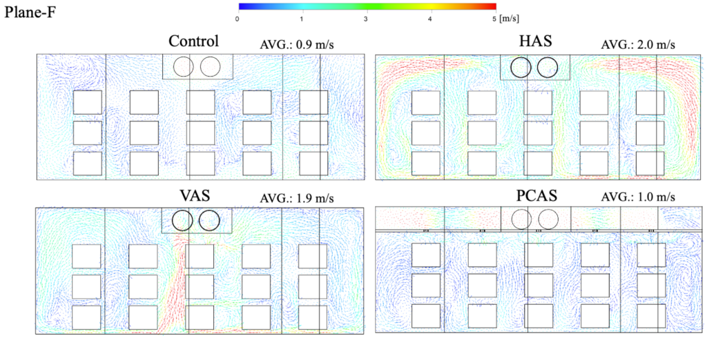
Measurements and CFD in commercial produce stores identified high- and low-velocity regions around stacks. This supports testing the loaded geometry rather than relying on an empty-room airflow pattern. [3]
Check the pressure penalty of every air guide
A baffle or duct changes system resistance. The analysis should therefore represent the selected fan pressure-flow curve and coil resistance, not assume unchanged airflow after adding an obstruction. Confirm that the resulting operating point remains within the equipment capability. Coordinate guides with cleaning, frost exposure, drainage and coil removal, and obtain manufacturer acceptance where required. A mechanically simple, removable guide is often a better candidate for field testing than an elaborate distribution system.
Read temperature results alongside airflow
In this study, horizontal supply reduced simulated seven-eighths cooling time by 18.8% relative to conventional supply. This is a cooling-time result, not a measured electricity saving. The model excluded infiltration and phase change and imposed supply flow, so it does not establish freezer frost behavior or the fan-power cost of ducting. [2]
Convert improved distribution into lower fan demand
After correcting poor coverage, test whether lower fan speed still meets the temperature and recovery requirements. Under approximate fan affinity laws, 80% speed corresponds to about 51% of full-speed fan power. This relationship concerns fan power, not total freezer electricity. Lower fan input can also reduce the heat released inside the refrigerated space. [4]
Specify compatible motors and controls, an approved minimum operating speed, and separate sequences where holding and recovery duties require them. Check coil performance and the most difficult storage locations at reduced speed. An airflow reduction that saves fan power but prolongs compressor operation or creates unacceptable warm pockets may not reduce total cost.
The Danish Technological Institute combined CFD, models and testing to investigate airflow and baffles in blast-freezing tunnels. Its findings support optimizing distribution and fan operation together. They also show that changes are not automatically additive: combining pallet relocation and baffling gave an unfavorable result in the test tunnel. The reported blast-freezing savings are not a prediction for commercial storage freezers. [5]
Model the operating events that matter
For a heavily used door, a steady closed-door model misses the main disturbance. A transient study can compare door-opening duration, fan operation during access, protective devices and the subsequent recovery. Moisture transport is needed to assess humidity entry; predicting frost accumulation and defrost requires additional physical models or measured coil data. An air-temperature contour alone does not justify reducing defrost frequency.
Use CFD selectively. Experimental research found little advantage over suitable empirical models for simple cold-store doorway infiltration, while identifying greater potential for time-varying conditions and door-protection devices. Begin with a conventional infiltration calculation when it answers the design question adequately. [6]
Turn the analysis into construction requirements
The final deliverable should be a coordinated mechanical layout and a verifiable operating sequence. Show evaporator locations, discharge directions, required return paths, maximum stock height, service clearances and any air-guide details. Compare full and partial stock and the agreed recovery condition. Record the assumptions that depend on the operator maintaining those arrangements.
At commissioning, verify equipment operation before diagnosing distribution: refrigerant conditions, coil condition, fan rotation, controls and defrost must be correct. Then map temperatures at the predicted critical locations under an agreed loading and door-use scenario. Define air-temperature limits separately from product-temperature limits. Measure electricity over representative operation if savings are claimed; a CFD plot is not an annual energy calculation.
For designers and contractors, the strongest business case is a specific decision resolved before it becomes field rework: choosing the evaporator arrangement, correcting a return path, avoiding an unnecessary auxiliary fan, or establishing a lower fan speed. Simple rectangular rooms may be served well by manufacturer guidance. CFD is most valuable where geometry, stock or operating disturbances make the outcome uncertain.
References
[4] Danfoss. Using VFDs in Refrigeration and Cold Storage Applications (4).